Interpreting PCIe Device to CPU Locality Information
Introduction
The purpose of this post is to illustrate the need for gathering and interpreting hardware locality information from modern multi-CPU servers. It is important for servers to expose NUMA node affinity information in ACPI tables correctly for both memory and PCIe devices in order for applications to properly adjust their behavior based on that information.
Problem Statement
There are use-cases for servers in which they form a base for complex networking setups in the telecommunications world. Specifically, network designs include usage of SR-IOV-capable NICs or SmartNICs for accelerating packet processing using specialized hardware in VNFs placed into virtual machines. A virtual machine hosting a VNF will typically need to be pinned to a CPU located closer to the PCIe network device it intends to use to avoid penalties associated with accessing a PCIe device over an inter-processor link (called “QPI” or “UPI” in Intel-based systems). Other use-cases include HPC involving GPU processing where data has to be copied between memory of PCIe devices.
For example, some servers have multi-root-complex designs while not being blade servers; likewise, they do not rely on non-transparent bridging (NTB) technology. Instead, they rely on a firmware-level technique to hide multiple root complexes from the operating system kernel (described below). There are servers which use such designs that have firmware-level limitations as they do not expose proximity information for PCIe devices attached to different CPUs as shown in the respective section below. As a result, it is not possible to schedule workloads with PCIe to NUMA node affinity in mind.
Multi-processor Systems and NUMA Node Affinity
Non-blade rack-mount server systems with contemporary CPU architectures (e.g. Intel Haswell and above) are generally built with multiple root complexes - every CPU has at least one PCIe port with which it attaches to a PCIe hierarchy. Each root complex has its own Host Bridge to connect a CPU with a PCIe hierarchy. Although the PCIe specification allows only one PCIe root to be present in a given hierarchy, it does not prevent a system as a whole from having multiple root complexes with their own Host Bridges servicing separate PCI domains. Hardware vendors use a technique to assign ranges of non-overlapping PCI bus IDs to Host Bridges connected to root complexes associated with different CPUs in multi-processor systems. Usage of non-overlapping address ranges allows the addressing scheme to represent a single contiguous PCI address space while in fact referring to isolated hierarchies. During device enumeration by the Linux kernel, bus id ranges are retrieved via _CRS (Current Resource Settings) ACPI object associated with a given Host Bridge.
To illustrate, a system with 2 CPUs could have the following setup:
- root complex 1: PCI bus ID range [0, 63];
- root complex 2: PCI bus ID range [64, 127].
There are no standard restrictions on the ID ranges (using powers of 2 is common but not mandatory) or on the number of root complexes per CPU (could be 2 complexes for CPU1 and one for CPU2) so long as an enumeration software implementation supports a given setup. “Configuration Software” or “Enumeration Software” referred to in this context by standards and books is usually a BIOS or UEFI implementation (pointers to relevant open source code: EDK2, coreboot, seabios).
Multi-processor systems have inter-CPU links which are used for both inter-node system memory transfers and system to device/device to system memory transfers which introduces affinity of PCIe devices to CPUs. Inter-CPU links are called QPI or UPI (newer) on Intel-based servers and are a vendor-specific standard (not PCIe compatible in terms of switching). This prevents direct peer-to-peer communication of PCIe devices and traversal of an inter-CPU link incurs additional overhead for Device-to-Host-to-Device communication as an OS driver needs to handle this by performing transfers to system memory from one device first and then to the target device.
Modern NUMA systems which implement ACPI normally (ask your vendor) describe the physical topology of a server via ACPI _PXM (proximity) objects associated with devices (see “6.2.14 _PXM (Proximity)” in the ACPI specification). This information is interpreted by the Linux kernel during enumeration and device nodes present in sysfs have a numa_node field exposed as a result (e.g. /sys/devices/pci0000:de/0000:ad:be.e/numa_node). In the OpenStack case this is used, for example, by Libvirt and Nova with Nova providing NUMA-aware scheduling not only from the memory perspective but also for PCIe devices that are passed through to virtual machines which is quite important for VNFs, GPU workloads and other applications requiring low-latency PCIe device access or peer-to-peer PCIe device communication.
There is also a useful ACPI table called SLIT (System Locality Distance Information Table) which describes relative distance between proximity domains (also referred to as “system localities”, see “5.2.17 System Locality Distance Information Table”). The number of proximity domains is exposed as “Number of System Localities”.
The maximum number of proximity domains is also reported in the Maximum System Characteristics Table (MSCT) as a 4-byte field (see 5.2.19). Interestingly, it is stored as maximum proximity domains minus one as the specification notes so it is better to check the source code of a tool you use to dump this table: if it does not modify this field, a value of 1 would mean that you have 2 proximity domains.
Maximum Number of Proximity Domains indicates the maximum number of Proximity Domains ever possible in the system. The number reported in this field is (maximum domains – 1). For example if there are 0x10000 possible domains in the system, this field would report 0xFFFF.
Summary of Communication Types
Subjectively, inter-device communication on a single server system could be subdivided into the following categories:
- system: communication traversing PCIe and a CPU interconnect (QPI/UPI);
- node: communication traversing PCIe and an interconnect between PCIe Host Bridges within a root complex associated with a single CPU. This implies traversal of PCIe switches along the way;
- PHB: PCIe Host Bridge - communication traversing a PCIe hierarchy and a PCIe Host Bridge (including the CPU);
- PXB: PCIe excluding host bridges - peer to peer communication between PCIe devices with one or multiple PCIe switches between them;
- PIX: PCIe crossing an internal switch - peer to peer communication between PCIe devices with one PCIe switch between them;
- PCIe single board - communication traversing a single on-board PCIe switch.
Analyzing Hardware Information
Useful Tooling
In order to better understand workload placement on a given server, some analysis needs to be performed via relevant tools:
- open-mpi community has created a useful project called hwloc which allows extracting available hardware location information from a system and representing it in a textual or graphical form. For Linux kernel this is done using nodes exposed in sysfs so if hwloc does not report proper placement information there is a good chance that the target system does not correctly provide it in ACPI tables (kernel or hwloc bugs are also possible but are subjectively less likely);
- fwts is a project by Colin Ian King @ Canonical that provides a test suite for firmware (BIOS, UEFI, ACPI) and some useful tooling, e.g. to dump ACPI tables in a human-readable form.
Vendor Documentation Example
Vendor documentation typically contains block diagrams of target systems. The block diagram below represents important information about affinity of certain devices to CPUs for a particular server model (vendor name is omitted on purpose):
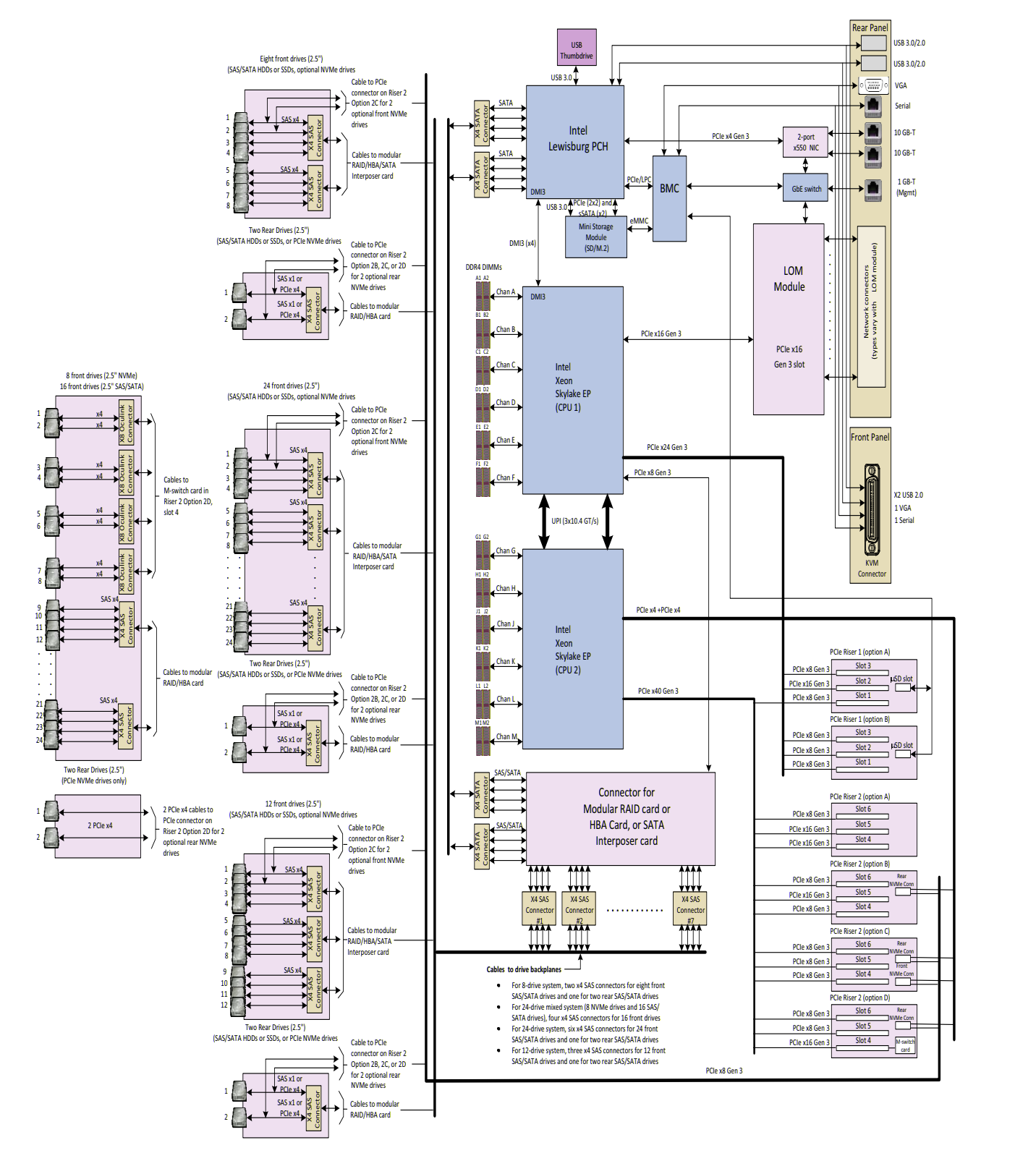
Specifically:
- CPU1
- BMC;
- LoM network interfaces;
- HBA card;
- PCH;
- Some PCIe slots;
- CPU2;
- NVMe devices (per block diagram lines and the vendor data sheet clearly mentions the following: “NVMe requires 2 CPUs”);
- Some PCIe slots.
System Inspection via hwloc, sysfs and acpidump
Let’s compare the documentation with what is extractable from the software perspective:
Bridge Host->PCI L#0 (P#0 buses=0000:[00-04])
# …
Bridge Host->PCI L#4 (P#1 buses=0000:[17-1a])
# …
Bridge Host->PCI L#7 (P#3 buses=0000:[5d-5e])As can be seen, hwloc shows that from the software perspective all 3 root complexes are connected to the same CPU which does not match the block diagram above.

The maximum proximity domains value stored in MSCT is equal to 1 which means that there are 2 proximity domains in total:
Max Proximity Domains : 00000001The number of system localities represented in the SLIT table is 2 which is consistent with MSCT:
[024h 0036   8]                   Localities : 0000000000000002
[02Ch 0044   2]                 Locality   0 : 0A 15
[02Eh 0046   2]                 Locality   1 : 15 0A
Although the block diagram clearly points out that NVMe devices require CPU2 to be present and are attached to the second CPU/NUMA node, all devices have affinity to CPU1 in sysfs.
lscpu | grep NUMA
NUMA node(s):        2
NUMA node0 CPU(s):   0-13,28-41
NUMA node1 CPU(s):   14-27,42-55

# PCIe card NIC (multi-function card, 1 physical card, 4 PCIe functions)
# PCI 8086:1572 (P#102400 busid=0000:19:00.0 class=0200(Ether)
# PCIDevice="Ethernet Controller X710 for 10GbE SFP+"
cat /sys/class/pci_bus/0000\:19/cpulistaffinity
0-13,28-41

# nvme
# PCI 1c58:0023 (P#385024 busid=0000:5e:00.0 class=0108(NVMExp)
cat /sys/class/pci_bus/0000\:5e/cpulistaffinity
0-13,28-41

# LoM NIC
# PCI 8086:1563 (P#4096 busid=0000:01:00.0 class=0200(Ether)
cat /sys/class/pci_bus/0000\:01/cpulistaffinity
0-13,28-41

# HBA
# PCI 1000:0014 (P#98304 busid=0000:18:00.0 class=0104(RAID)
# PCIVendor="LSI Logic / Symbios Logic"
# PCIDevice="MegaRAID Tri-Mode SAS3516")
cat /sys/class/pci_bus/0000\:18/cpulistaffinity
0-13,28-41
Hardware Information Summary
- 3 PCIe hierarchies (3 entries titled
Bridge Host->PCI); - No proper proximity (ACPI PXM) information exposed - all devices are associated with CPU1;
- The block diagram from the data sheet is clearly different from the hwloc/lstopo output which confirms that location information is not exposed correctly:
Bridge Host->PCI L#7 (P#3 buses=0000:[5d-5e]);- The NVMe device has a bus id equal to 5e:
PCI 1c58:0023 (P#385024 busid=0000:5e:00.0 class=0108(NVMExp) PCIVendor="HGST, Inc.") "HGST, Inc.";
- BMC and LoM network interfaces (eno1 and eno2) are attached to CPU1 based on the diagram:
Bridge Host->PCI L#0 (P#0 buses=0000:[00-04]);PCI 8086:1563 (P#4096 busid=0000:01:00.0 class=0200(Ether) PCIVendor="Intel Corporation" PCIDevice="Ethernet Controller 10G X550T") "Intel Corporation Ethernet Controller 10G X550T" Network L#0 (Address=8a:6d:22:f7:f2:87) "eno1";- Bus id 01 of eno1 network device fits into the 00-04 bus id range;
PCI 102b:0522 (P#16384 busid=0000:04:00.0 class=0300(VGA) PCIVendor="Matrox Electronics Systems Ltd." PCIDevice="MGA G200e [Pilot] ServerEngines (SEP1)");- Bus id 04 of a BMC VGA device fits into that range;
- Based on the block diagram the HBA is attached to CPU1;
- Which means that
Bridge Host->PCI L#4 (P#1 buses=0000:[17-1a])is attached to CPU1 as well; - Bus id 18 of the HBA fits into that range.
- Which means that
Inferred PCIe root complex mapping:
- P#0 -> CPU1;
- P#1 -> CPU1;
- P#2 -> CPU2.
Conclusion
For this particular server, there is no way to programmatically find out the association of PCIe devices with NUMA nodes and information represented in node_node sysfs entries will not be useful for applications such as libvirt or Nova. For this particular server build this problem is not going to be critical because there is one 4-port network card which has the correct affinity with CPU1 and pinning workloads to CPU1 will be appropriate. However, in other builds, where there may be network cards attached to CPU1 and CPU2, this will be problematic as it will not be possible to pin a workload to a correct CPU based on PCIe device affinity based on information retrievable via sysfs.
This information is very valuable for real-world large-scale projects at the hardware selection phase. Even if it is possible to fix the exposed ACPI information, operationally, a large firmware update can be problematic with the downtime it incurs.
Comparison to a Different System
In comparison, a different server system with 2 CPU sockets and root complexes does not report the maximum amount of proximity domains in MSCT, however, it does so in SLIT and also provides the necessary PXM information for PCIe devices. Specifically, this system has two GPU PCIe cards each of which has 2 GPUs connected via an on-card PCIe switch (2 cards show up as 4 PCIe devices as a result) and they are attached to two different root complexes which is important if data is to be copied between GPUs.

[024h 0036   8]                   Localities : 0000000000000002
[02Ch 0044   2]                 Locality   0 : 0A 15
[02Eh 0046 2] Locality 1 : 15 0A<object type="Bridge" os_index="48" name="Intel Corporation Xeon E7 v3/Xeon E5 v3/Core i7 PCI Express Root Port 3" bridge_type="1-1" depth="1" bridge_pci="0000:[04-07]" pci_busid="0000:00:03.0" pci_type="0604 [8086:2f08] [0000:0000] 02" pci_link_speed="0.000000">
<info name="PCIVendor" value="Intel Corporation"/>
<info name="PCIDevice" value="Xeon E7 v3/Xeon E5 v3/Core i7 PCI Express Root Port 3"/>
<object type="Bridge" os_index="16384" name="PLX Technology, Inc. PEX 8747 48-Lane, 5-Port PCI Express Gen 3 (8.0 GT/s) Switch" bridge_type="1-1" depth="2" bridge_pci="0000:[05-07]" pci_busid="0000:04:00.0" pci_type="0604 [10b5:8747] [0000:0000] ca" pci_link_speed="0.000000">
<info name="PCIVendor" value="PLX Technology, Inc."/>
<info name="PCIDevice" value="PEX 8747 48-Lane, 5-Port PCI Express Gen 3 (8.0 GT/s) Switch"/>
<info name="PCISlot" value="0-4"/>
<object type="Bridge" os_index="20608" name="PLX Technology, Inc. PEX 8747 48-Lane, 5-Port PCI Express Gen 3 (8.0 GT/s) Switch" bridge_type="1-1" depth="3" bridge_pci="0000:[06-06]" pci_busid="0000:05:08.0" pci_type="0604 [10b5:8747] [0000:0000] ca" pci_link_speed="0.000000">
<info name="PCIVendor" value="PLX Technology, Inc."/>
<info name="PCIDevice" value="PEX 8747 48-Lane, 5-Port PCI Express Gen 3 (8.0 GT/s) Switch"/>
<object type="PCIDev" os_index="24576" name="NVIDIA Corporation GK210GL [Tesla K80]" pci_busid="0000:06:00.0" pci_type="0302 [10de:102d] [10de:106c] a1" pci_link_speed="0.000000">
<info name="PCIVendor" value="NVIDIA Corporation"/>
<info name="PCIDevice" value="GK210GL [Tesla K80]"/>
<object type="OSDev" name="renderD128" osdev_type="1"/>
<object type="OSDev" name="card1" osdev_type="1"/>
</object>
</object>
<object type="Bridge" os_index="20736" name="PLX Technology, Inc. PEX 8747 48-Lane, 5-Port PCI Express Gen 3 (8.0 GT/s) Switch" bridge_type="1-1" depth="3" bridge_pci="0000:[07-07]" pci_busid="0000:05:10.0" pci_type="0604 [10b5:8747] [0000:0000] ca" pci_link_speed="0.000000">
<info name="PCIVendor" value="PLX Technology, Inc."/>
<info name="PCIDevice" value="PEX 8747 48-Lane, 5-Port PCI Express Gen 3 (8.0 GT/s) Switch"/>
<object type="PCIDev" os_index="28672" name="NVIDIA Corporation GK210GL [Tesla K80]" pci_busid="0000:07:00.0" pci_type="0302 [10de:102d] [10de:106c] a1" pci_link_speed="0.000000">
<info name="PCIVendor" value="NVIDIA Corporation"/>
<info name="PCIDevice" value="GK210GL [Tesla K80]"/>
<object type="OSDev" name="renderD129" osdev_type="1"/>
<object type="OSDev" name="card2" osdev_type="1"/>
</object>
</object>
</object>
</object><object type="Bridge" os_index="532480" name="PLX Technology, Inc. PEX 8747 48-Lane, 5-Port PCI Express Gen 3 (8.0 GT/s) Switch" bridge_type="1-1" depth="2" bridge_pci="0000:[83-85]" pci_busid="0000:82:00.0" pci_type="0604 [10b5:8747] [0000:0000] ca" pci_link_speed="0.000000">
<info name="PCIVendor" value="PLX Technology, Inc."/>
<info name="PCIDevice" value="PEX 8747 48-Lane, 5-Port PCI Express Gen 3 (8.0 GT/s) Switch"/>
<info name="PCISlot" value="0-6"/>
<object type="Bridge" os_index="536704" name="PLX Technology, Inc. PEX 8747 48-Lane, 5-Port PCI Express Gen 3 (8.0 GT/s) Switch" bridge_type="1-1" depth="3" bridge_pci="0000:[84-84]" pci_busid="0000:83:08.0" pci_type="0604 [10b5:8747] [0000:0000] ca" pci_link_speed="0.000000">
<info name="PCIVendor" value="PLX Technology, Inc."/>
<info name="PCIDevice" value="PEX 8747 48-Lane, 5-Port PCI Express Gen 3 (8.0 GT/s) Switch"/>
<object type="PCIDev" os_index="540672" name="NVIDIA Corporation GK210GL [Tesla K80]" pci_busid="0000:84:00.0" pci_type="0302 [10de:102d] [10de:106c] a1" pci_link_speed="0.000000">
<info name="PCIVendor" value="NVIDIA Corporation"/>
<info name="PCIDevice" value="GK210GL [Tesla K80]"/>
<object type="OSDev" name="card3" osdev_type="1"/>
<object type="OSDev" name="renderD130" osdev_type="1"/>
</object>
</object>
<object type="Bridge" os_index="536832" name="PLX Technology, Inc. PEX 8747 48-Lane, 5-Port PCI Express Gen 3 (8.0 GT/s) Switch" bridge_type="1-1" depth="3" bridge_pci="0000:[85-85]" pci_busid="0000:83:10.0" pci_type="0604 [10b5:8747] [0000:0000] ca" pci_link_speed="0.000000">
<info name="PCIVendor" value="PLX Technology, Inc."/>
<info name="PCIDevice" value="PEX 8747 48-Lane, 5-Port PCI Express Gen 3 (8.0 GT/s) Switch"/>
<object type="PCIDev" os_index="544768" name="NVIDIA Corporation GK210GL [Tesla K80]" pci_busid="0000:85:00.0" pci_type="0302 [10de:102d] [10de:106c] a1" pci_link_speed="0.000000">
<info name="PCIVendor" value="NVIDIA Corporation"/>
<info name="PCIDevice" value="GK210GL [Tesla K80]"/>
<object type="OSDev" name="card4" osdev_type="1"/>
<object type="OSDev" name="renderD131" osdev_type="1"/>
</object>
</object>
</object>$ cat /sys/class/pci_bus/0000\:06/cpuaffinity
00ff
$ cat /sys/class/pci_bus/0000\:07/cpuaffinity
00ff
$ cat /sys/class/pci_bus/0000\:84/cpuaffinity
ff00
$ cat /sys/class/pci_bus/0000\:85/cpuaffinity
ff00
$ cat /sys/class/pci_bus/0000\:06/device/numa_node
0
$ cat /sys/class/pci_bus/0000\:07/device/numa_node
0
$ cat /sys/class/pci_bus/0000\:84/device/numa_node
1
$ cat /sys/class/pci_bus/0000\:85/device/numa_node
1